Introduction
EMMUA 214 States: Page 20
3.6.1 Definitions
Type of Protection ‘i’ is a protection type in which the energy available in the hazardous area is limited to a level below that which could ignite a flammable atmosphere. Intrinsically safe equipment is electrical equipment in which all the circuits are intrinsically safe circuits.
Associated equipment is electrical equipment which contains both intrinsically safe circuits and non-intrinsically safe circuits and is constructed so that the non-intrinsically safe circuits cannot adversely affect the intrinsically safe circuits.
3.6.2 Standards and selection
i) Current standards
- IEC 60079-11 (EN 60079-11) Explosive atmospheres Part 11: Equipment protection by intrinsic safety
- IEC 60079-25 (EN 60079-25) Electrical apparatus for explosive gas atmospheres - Part 25: Intrinsically safe systems.
ii) Superseded standards
- EN 50020 Intrinsic safety ‘i’;
- EN 50039 Intrinsically safe electrical systems ‘i’.
- BS 5501 Part 7 Intrinsic safety ‘i’.
- BS 5501 Part 9 Intrinsically safe electrical systems ‘i ‘’
iii) EPL/category and zones of use Intrinsically safe apparatus may be used in areas requiring EPL ‘Ga’ , ‘Gb’ and ‘Gc’, or Category 1, 2 and 3. Prior to 2007 it was permitted to use such equipment in Zones 0, 1 or 2.
Three levels of protection are considered: ‘ia’, ‘ib’ and ‘ic’,
The essential difference between the three levels of protection lies in component integrity and in the means adopted to ensure that, even if components do fail, safety is ensured. Level of protection ‘ia’ has the highest integrity.
Note: The term ‘level of protection’ has been used since the advent of ATEX to replace the term ‘category’.
Intrinsically safe apparatus to level of protection ‘ia t is designed for use in areas requiring EPL ‘Ga’ or Category 1. Equipment to level of protection ‘ib’ is designed for use in areas requiring EPL ‘Gb’ or Category 2. It therefore cannot be used in areas requiring EPL ‘Ga’ or Category 1 equipment.
It can be used in areas requiring EPL ‘Gc’ or Category 3. Equipment to level of protection t ic’ is designed for use only in areas requiring EPL ‘Gc’ or Category 3.
Note: Whilst it is essential that the level of protection, and hence the EPL/Category, has to match the requirements of the location of the equipment, it is not the only criteria. Intrinsic safety is a system concept. An interconnection of Ex ‘ib’ equipment does not necessarily create an Ex ‘ib’ system.
3.6.3 Construction and use
i) Safety Barriers
Two basic types of barrier are in use: the shunt diode barrier and the galvanically isolated barrier a) a) Shunt Diode Safety Barrier
A basic shunt diode safety barrier, more often called a Zener barrier, includes as an absolute minimum the components shown below.
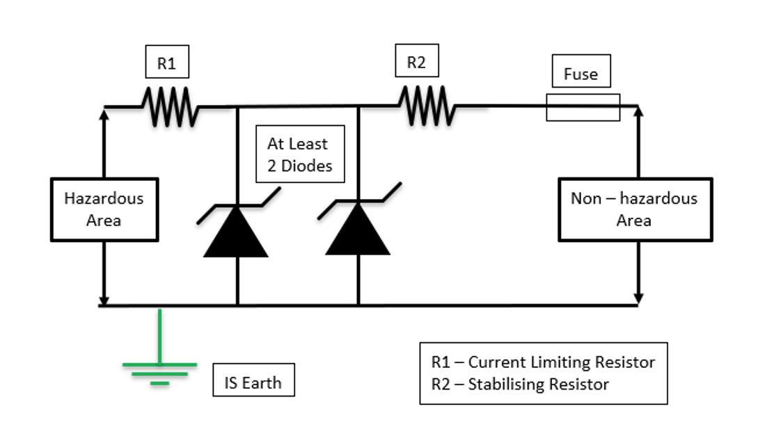
The requirements of intrinsic safety is met by providing current and voltage limitation in the hazardous circuit. b) Galvanically Isolated Barriers
Galvanically isolated barriers allow transference of energy without any directly wired interconnection. An intrinsically safe earth connection is not normally required.
ii) Clearances
a) Between Terminals of Intrinsically Safe and Non-Intrinsically Safe Equipment
The clearance distance should be not less than 50 mm.
b) Between Bare Conducting Parts of Terminals of Separate Intrinsically Safe Circuits
The clearance distance should be not less than 6 mm.
c) Clearances to Earth
The clearance distance from bare conducting parts of external conductors connected to a terminal, to any earthed metal (or other conducting parts) should not be less than 3 mm.
iii) Earthing
Any system requiring different types of intrinsically safe equipment should have an overall policy on earthing. It is good practice not to mix diode and galvanic barriers on the same mounting rail.
a) The Intrinsic Safety Earth
The intrinsic safety earth is a high integrity dedicated earth. It is used to provide a direct connection between the earth terminal of shunt diode safety barriers and the mains power supply system earth. It is to comply with the following:
- Insulation of Dedicated Earth
Insulation is required to prevent invasion by fault currents which might flow in metallic parts with which an un-tnsulated earth conductor (if used) could come into contact.
- Mechanical protection for Earth Conductor
Mechanical protection should be provided where there is a danger of damage, e.g. from passing traffic etc.
- Impedance to Earth
Current practice suggests that a value of 0.1Ω for the earth impedance is desirable. However the standard permits an impedance of up to 1.0Ω.
- Earth Conductor Minimum Size
The minimum size is 4 mm. This may need to be increased to maintain the required low impedance. The provision of two earth conductors should be considered to facilitate testing.
b) Earthing of Screens
Particular importance is placed on the earthing of screens. These should always be earthed in accordance with the ‘hook up’ or installation diagrams. Preferably, they should be earthed in the non-hazardous area.
iv) Surge Suppression
Surge suppression units, when specified, are to be installed as close as practicable to the equipment being protected.
v) Unused Cores
All unused cores should be terminated at both ends, through connected at any intermediate junction accordance with the installation diagram.
vi) Insulation Resistance Measuring
Insulation tests on cables should only be undertaken using approved measuring equipment. Use of incorrect or unsuitable measuring equipment may damage sensitive electronic equipment. Inspection schedules provide appropriate details. Appropriate precautions need to be taken when testing cables from the non-hazardous area, to ensure incendive sparking does not occur within the hazardous area.
Intrinsic Safety is a widely used method of explosion protection. It is used for very low power applications only, the typical examples are control and instrumentation circuits.
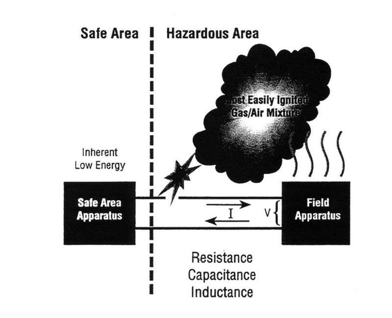
An Intrinsic Safety circuit is a circuit in which no spark or any thermal (heating) effect produced is capable of causing ignition of a given explosive atmosphere.
This is based upon restricting electrical energy within the apparatus and also the interconnecting wiring.
The Intrinsic Safety concept works by limiting the energy of sparks and keeping surface temperature down.
Because of the method of which Intrinsic Safety is achieved, it is necessary to ensure that not only the electrical apparatus exposed to the explosive gas atmosphere, but also other electrical apparatus with which it is interconnected is suitably constructed.